From Hugging Face to vLLM: A Verifiable Model Integration Pipeline
A model being able to run inference in Hugging Face only proves that its original implementation works. To bring it into vLLM, module naming, runtime inputs, parallel parameters, weight loading, registration information, and test evidence must all be aligned.
Source video: Bilibili BV1gYL965ERP · Slides: vLLM Model Integration Guide
This article is intended for engineers who have a basic understanding of PyTorch, Transformers, and Hugging Face but are not yet familiar with implementing models in vLLM.
Intended Audience and Prerequisites
Before reading, you should ideally be able to:
- Read
nn.Module,forward, andstate_dict; - Understand Embedding, Attention, Q/K/V, FFN, and LM Head;
- Understand GPU memory, tensor sharding,
all-reduce, andall-gather; - Understand the basic organization of Hugging Face checkpoints and
modeling_*.py.
Learning Objectives
After reading this article, you should be able to:
- Establish an end-to-end integration path from selecting a reference implementation to registration and testing;
- Understand how
prefix, flattened token inputs, and vLLMAttentionwork together; - Select tensor-parallel layers based on data layout and identify the corresponding communication boundaries;
- Understand why merging parallel parameters requires corresponding changes to
load_weights; - Distinguish successful registration, successful dummy-weight initialization, and correct real-world inference;
- Identify additional constraints introduced by multimodality, ASR, sliding windows, and Mamba.
The following three levels of factual confidence are used throughout:
- Source-backed fact: directly supported by the presentation slides or fact ledger;
- Maintainer experience: engineering guidance from the transcript;
- To be verified: not fully specified by the source material and must be confirmed against the target version and specific model.
1. Narrow the Problem First: What Actually Needs to Change During Model Integration?
The real engineering conflict is that model code may run in Hugging Face but cannot be used directly in vLLM’s serving path.
The source material uses PagedAttention—a runtime mechanism presented to explain KV-Cache utilization—and parallel layers to illustrate the value of integration. However, switching runtimes does not automatically make a model comply with the new interfaces. Developers must still handle code migration, module naming, input layouts, parallel parameters, weight mapping, registration, and testing.
The following diagram separates “why integration is worthwhile” from “what must actually be changed in the model,” avoiding the mistake of turning the source material’s qualitative motivations into performance guarantees after integration.

Figure 1: Motivation and engineering work for vLLM integration. Source: PPT page 3.
The two nodes on the left explain the motivation for integration, while the four nodes on the right represent the work that the model implementation must actually complete. The two dashed lines emphasize that PagedAttention and parallel layers can explain the value of integration, but they cannot automatically solve interface, parameter, or weight-related problems.
The source material does not provide the model version, hardware, degree of parallelism, concurrency, throughput, latency, or GPU memory data. Therefore, this article makes no quantitative performance claims.
Start from a Similar Implementation
When integrating a model, first look for an existing model with the most similar architecture in vllm/model_executor/models/, focusing on:
- How Attention and the FFN are organized;
- The weight layouts of Q, K, V, gate, and up;
- Inputs, outputs, and generation modes;
- Whether the model contains a multimodal tower, per-layer sliding windows, or special state.
Similar names do not imply architectural compatibility. A similar implementation is only a template; it does not replace inspection of the configuration, module hierarchy, and checkpoint weight keys.
If no suitable template exists, migrate from Hugging Face’s modeling_*.py. During migration, preserve the original copyright and license headers. After confirming dependencies, remove training paths that are unnecessary for inference, such as loss, labels, and gradient checkpointing.
Five Stages Form a Dependency Chain
The following diagram provides a map of the entire article. It is useful to examine the complete pipeline first because interface adaptation, parallel layout, and weight loading are not independent changes: each preceding stage directly constrains how the next stage can be implemented.

Figure 2: The five-stage model integration workflow. Source: PPT page 4.
The solid lines from left to right represent the primary dependencies: the runtime interface determines how the model is constructed and executed, parallel layers change the physical organization of parameters, and the new parameter organization determines how checkpoint weights must be written.
The reverse dashed lines indicate that development is not a strictly waterfall process. For example, if names cannot be mapped reliably while designing load_weights, the module hierarchy or parallel parameter names may need to be revised.
A verification sequence that better isolates failures is:
The model can be constructed
→ Single-GPU weights can be loaded
→ Single-GPU forward can execute
→ Introduce tensor parallelism
→ Complete registration
→ Compare real behavior
If tensor parallelism is enabled before single-GPU forward works, one failure may simultaneously involve input shapes, parameter sharding, and cross-GPU communication. Establishing a single-GPU baseline first makes it easier to narrow multi-GPU issues down to layout and synchronization paths.
2. Entering the Runtime: prefix and the Flattened Token Interface
Similar model architectures do not imply identical runtime contracts. Before entering vLLM, at least two questions must be answered:
- How does every internal module obtain a stable and unique identity?
- How does the model consume the flattened token stream supplied by the scheduler?
The former is connected through prefix, while the latter is primarily reflected in embed_input_ids, forward, and vLLM Attention.
prefix Is a Module’s Coordinate in the Naming Tree
prefix is the hierarchical name received when an internal module is constructed. It should generally align with the module’s full path in state_dict. It is used to form the fully qualified registration name of Attention and may also participate in quantization configuration matching.
It is useful to examine the module tree first because whether a local name is correct depends on its complete propagation path from the top level to the current node.

Figure 3: prefix propagation through the module tree. Source: PPT page 6.
The solid lines from model to model.layers.0.self_attn represent the construction hierarchy. The dashed lines to state_dict, the quantization configuration, and the registry represent the different runtime responsibilities carried by the same name.
A minimal naming tree can be written as:
If layer 0 and layer 1 incorrectly share model.self_attn, two different Attention modules will receive the same registration name. The correct approach is to preserve the actual hierarchy:
Another possible issue is a divergence between the runtime naming tree and the checkpoint weight tree:
The two may refer to similar structures, but their fully qualified names are inconsistent, creating ambiguity in weight mapping and quantization configuration matching.
The constructor code in the source material only demonstrates name propagation. It does not fully show how some vllm_config values are passed, and concatenating an empty prefix may introduce a leading period. The specific helper functions and constructor signatures must be verified against the target version.
From Two-Dimensional Batches to a Flattened Token Stream
The naming tree solves “how the runtime identifies modules,” while the input interface solves “how scheduling results enter the model.”
The following comparison diagram presents three confirmed changes together: adding an embedding entry point, flattening token and position inputs, and removing training paths while calling vLLL Attention.
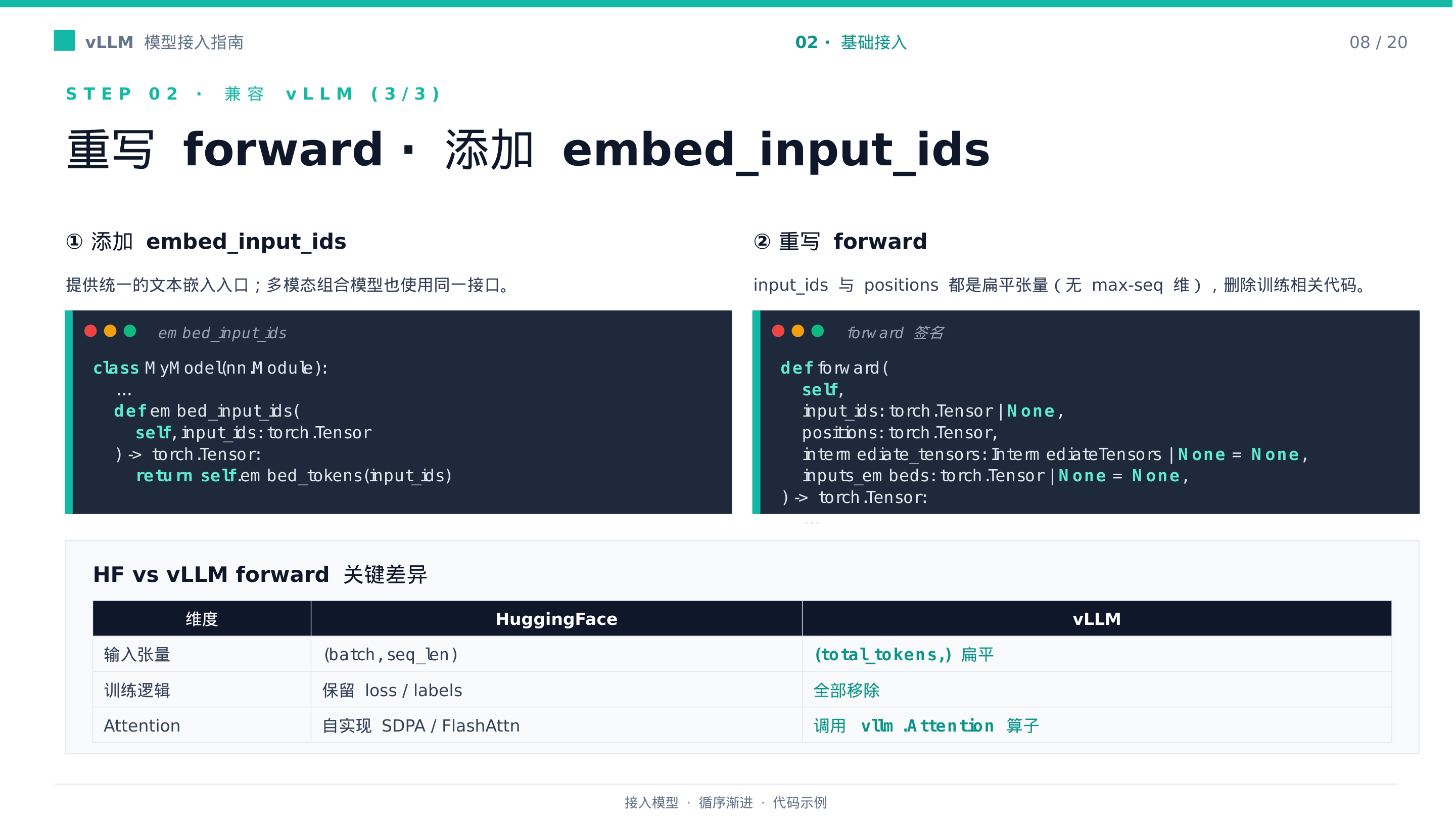
Figure 4: Changes to the Hugging Face and vLLM model entry points. Source: PPT page 8.
The left side shows the common two-dimensional batch entry point in Hugging Face, while the right side shows vLLM’s flattened token entry point for scheduler output. embed_input_ids converts input_ids into text embeddings, after which execution continues through forward and vLLM Attention.
The interface changes explicitly supported by the source material are as follows:
| Interface | Common Hugging Face form | vLLM integration form |
|---|---|---|
| Token input | (batch, seq_len) |
(total_tokens,) |
| Position input | Organized by batch and sequence | positions corresponding to flattened tokens |
| Text embedding | May call the internal embedding layer directly | Provides embed_input_ids |
| Attention | The model’s own implementation | vLLM Attention |
| Training logic | May include labels and loss |
Remove branches unnecessary for inference |
Flattening does not mean that request boundaries or length constraints disappear. It only means that this information is no longer represented through an explicit batch × max_seq input dimension.
The source material does not elaborate on request-boundary metadata or provide complete shapes for all optional inputs and outputs. Therefore, the one-dimensional entry-point convention cannot be extrapolated to every tensor in the model.
The completion criteria for this section are that names propagate through the actual module tree, Attention registration names do not conflict, weight paths can be cross-checked, and the model can accept flattened token inputs. Tensor parallelism can then be introduced so that the new variables are primarily limited to sharding and communication.
3. Scaling from One GPU to Multiple GPUs: Selecting Parallel Layers by Data Layout
Tensor Parallelism (TP) addresses scenarios in which model weights cannot fit on a single GPU. It shards parameters along the input, output, or vocabulary dimension of the weights, allowing multiple GPUs to jointly execute a forward pass.
When selecting a parallel layer, it is not enough to check whether the original layer is a Linear. Four factors must also be tracked:
- Along which dimension the weight is sharded;
- Whether the current device produces the complete output or a local shard;
- Whether the next layer can directly consume that layout;
- Where cross-GPU synchronization is required.
The following table serves as an index for this section. Parameter organization, communication behavior, and use cases are presented together to prevent implementations from being replaced mechanically based only on layer names.
| Parallel layer | Confirmed parameter organization | Confirmed communication behavior | Typical use |
|---|---|---|---|
ColumnParallelLinear |
Sharded along the output dimension | The current layer retains column-distributed output | Projections that must be sharded along the output dimension |
RowParallelLinear |
Sharded along the input dimension | Executes all-reduce after computation |
The second FFN layer and O-Proj |
MergedColumnParallelLinear |
Merges multiple column-parallel projections | The current layer does not synchronize immediately | Structurally compatible SwiGLU gate and up projections |
QKVParallelLinear |
Merges Q, K, and V before parallel sharding | The current layer does not synchronize immediately; KV-head replication may be involved | Q/K/V projections |
VocabParallelEmbedding |
Sharded along the vocabulary dimension | Executes all-reduce |
Input Embedding |
ParallelLMHead |
Replaces the LM Head | The specific layout and communication behavior are not confirmed in the fact ledger | Output projection |
Table 1: Sharding, communication, and uses of parallel layers. Reconstructed from PPT page 10.
“Does not synchronize immediately” in the table means only that the current layer retains distributed output. It does not imply that the subsequent inference path performs no communication. The source material also does not explain the specific distributed layout of ParallelLMHead, so it cannot be inferred from other vocabulary-parallel components.
Why Column Parallelism and Row Parallelism Are Often Adjacent
Let a linear layer be:
Y = XW
where the input dimension of W is d_in and its output dimension is d_out.
If two GPUs shard W along the output dimension, the weight can be represented as:
W = [W₀ W₁]
The two GPUs produce XW₀ and XW₁, respectively, which together form an output distributed along the output dimension. As long as the next operation can continue consuming this sharded representation, the current layer does not need to aggregate it immediately.
If the weight is sharded along the input dimension, the input is correspondingly divided into:
X = [X₀ X₁]
The two GPUs compute X₀W₀ and X₁W₁, respectively. These are only partial sums of the complete result, so they must be added using all-reduce.
This produces a typical data flow:
QKV or FFN up projection
→ Produce shards along the output dimension
→ Intermediate computation continues to consume the shards
→ O-Proj or FFN down projection consumes shards along the input dimension
→ all-reduce combines the partial sums
The communication point is determined by the data layout and cannot be inferred solely from the module name.
QKVParallelLinear merges the Q, K, and V projections before sharding them. The source material notes that KV-head replication may be involved, but it does not specify the triggering conditions, the relationship between TP size and the number of KV heads, or the exact tensor shapes on each GPU.
MergedColumnParallelLinear can merge the gate and up projections of SwiGLU, provided that the original model’s architecture and weight organization match this form. It is not a mechanical replacement for the first layer of every FFN.
The source material also states that parallel Linear layers support linear_method, through which a quantization scheme can be injected. This conclusion applies only to parallel Linear layers and cannot be extended to Embeddings, processors, or other model components.
Once TP is introduced, both the names and the physical organization of model parameters change. load_weights must be updated accordingly; otherwise, projections stored separately in the checkpoint cannot be loaded correctly into merged parameters.
4. Aligning the Checkpoint with Merged Parameters
The core responsibility of load_weights is not to open the checkpoint but to establish an exact mapping among three elements:
Checkpoint parameter name
↔ Current model parameter name
↔ Logical shard within the merged parameter
Here, a shard refers to a logical partition within the target parameter, not a checkpoint file shard on disk.
The following three-stage diagram separates name matching from tensor writing: load_weights selects the first two stages, while the target parameter’s own loader executes the final stage.
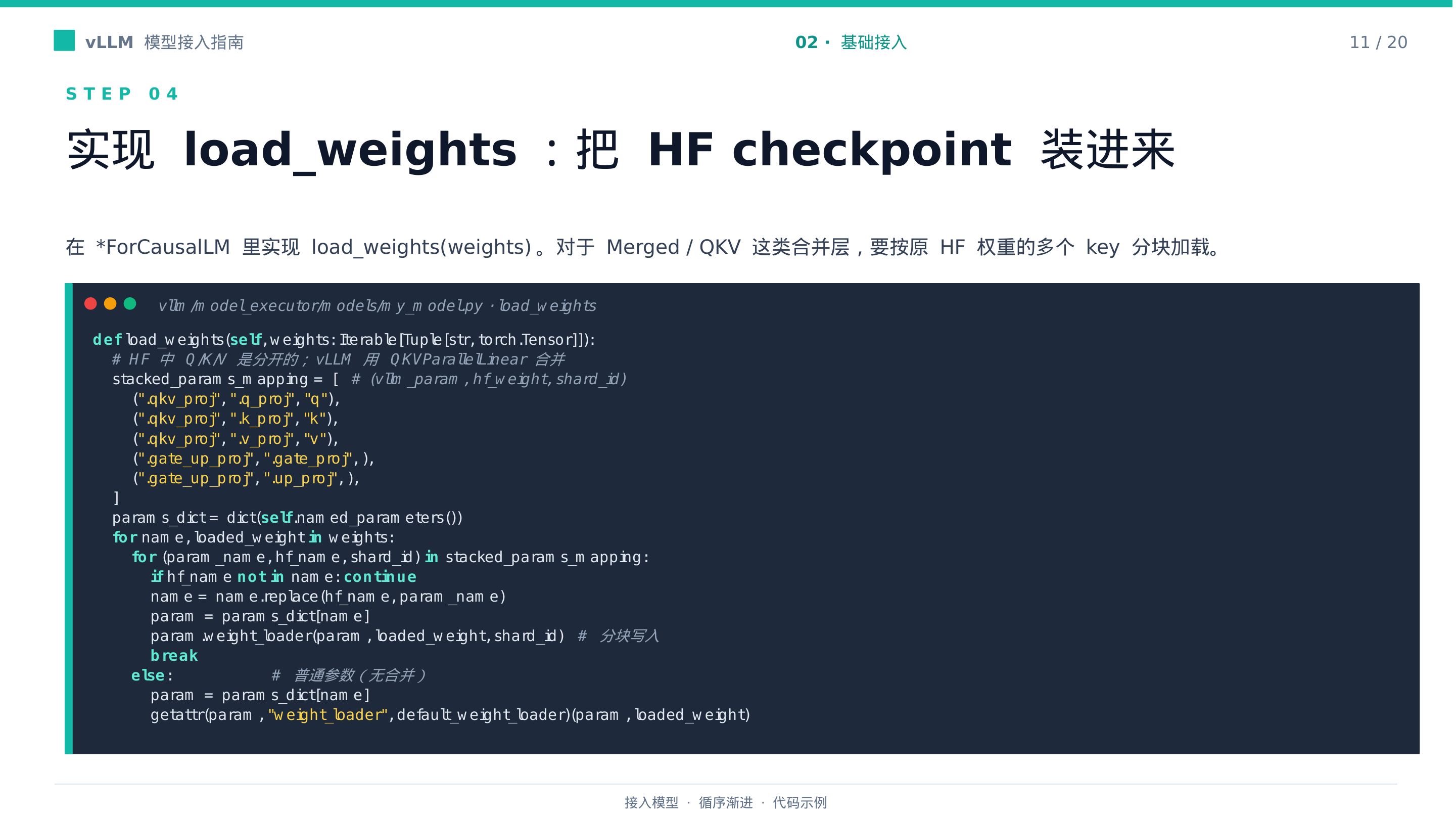
Figure 5: load_weights and stacked mapping. Source: PPT page 11.
The three nodes on the left are the Q, K, and V weights stored separately in the checkpoint. The rules in the middle select both the target parameter name and the logical shard. The weight_loader on the right is then responsible for writing each tensor into the correct location.
For example, suppose the source weight name is:
The mapping rule converts the target name to:
It then calls the target parameter’s weight_loader with shard_id="k".
The source material does not explain the write axis, offset, target tensor layout, or multi-GPU storage method. These behaviors are encapsulated in the target loader and cannot be inferred from names alone.
Branching Between Merged and Ordinary Parameters
The example uses Python for-else to distinguish two paths. When iterating over an individual checkpoint weight, the state transitions can be summarized as:
| Decision result | Loading action | Subsequent control flow |
|---|---|---|
| A stacked mapping matches | Convert the target name and call the target loader with shard_id |
break, skipping the ordinary path |
| No mapping matches | Look up an ordinary parameter with the same name | Enter the else branch of for-else |
| The ordinary parameter has a specialized loader | Call the parameter’s own weight_loader |
The current weight is complete |
| The ordinary parameter has no specialized loader | Call default_weight_loader |
The current weight is complete |
break prevents a weight from entering the ordinary path after it has already been handled by the merged path. Entering else does not indicate failure; it only means that the current weight does not belong to any of the listed merged projections.
If the model uses MergedColumnParallelLinear, gate_proj and up_proj must also be written into gate_up_proj. The source material confirms the merge relationship, but the demonstration slide does not provide legible shard identifiers. The specific values are therefore to be verified and must not be copied from the string conventions used for Q, K, and V.
Loading Without Errors Does Not Mean Loading Is Complete
Weight verification has at least three levels:
- The source name can be mapped to a parameter in the current model;
- The target loader accepts the tensor and completes a write;
- Every required parameter and internal shard is covered, with no unexpected checkpoint weights left unconsumed.
If the QKV mapping omits v_proj, Q and K may still be written successfully. Merely checking whether individual calls raise errors does not prove complete coverage.
Maintainer experience recommends tracking loaded, unloaded, and unconsumed weights and modifying load_weights based on an existing implementation with a similar architecture. The source material does not provide a stable checker API or return value, nor does it provide enough information to explain the MoE loading algorithm here.
Once the architecture, interfaces, and weight paths are aligned, the model must still be made discoverable by the framework. Registration and testing come next, but an important distinction must be maintained: being found by the framework and behaving correctly are two different conclusions.
5. Making the Framework Find the Model—and Proving Its Behavior Is Correct
This stage involves two questions:
- How does vLLM locate the model class from the architecture name in the checkpoint?
- Once the model is found, how can its real behavior be proven correct?
Built-in Registration and Plugin Registration
The following dual-path diagram places the architecture name, module, class object, and lazy-loading string in the same frame of reference, making the respective responsibilities of the two registration approaches clear.
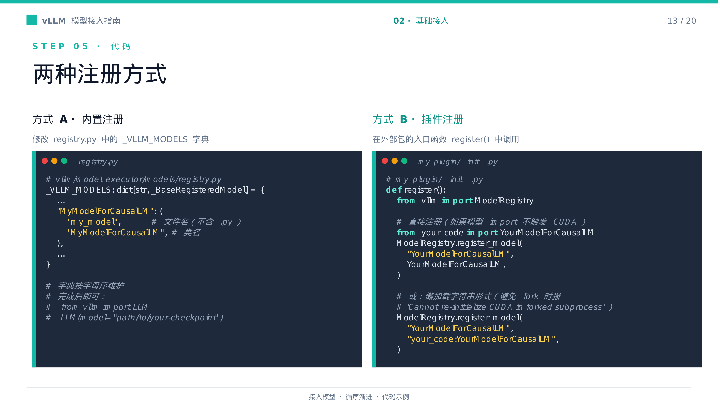
Figure 6: Built-in and plugin registration. Source: PPT page 13.
The built-in path begins with the checkpoint architecture name, enters _VLLM_MODELS, and then resolves the module file and model class. The implementation resides in vllm/model_executor/models/. Registration entries are maintained in alphabetical order, and the supported-model documentation must also be updated.
The plugin path calls ModelRegistry.register_model without modifying vLLM’s core code. It can either pass the model class directly or pass a "module:class_name" string.
If importing the model class triggers CUDA initialization, the string form can defer loading and avoid CUDA reinitialization conflicts in forked child processes. This form addresses a specific import risk and is not mandatory for all plugin registrations.
Regardless of the path used, registration proves only that the architecture name can be resolved. It does not prove that the configuration, weight mapping, or computation is correct.
Test Evidence Must Be Layered
The following matrix distinguishes the evidence provided by three categories of tests. This separation matters because successful initialization, agreement on real numerical behavior, and correctness of specialized paths cannot substitute for one another.
| Level | Verification target | What it can prove | What it cannot prove |
|---|---|---|---|
| REQUIRED | Registry example and dummy weights | The architecture can be resolved, and the initialization or basic loading path can execute | Real weights and outputs are correct |
| RECOMMENDED | Comparison of real generation, logprobs, or Pooling | Covered behavior matches or approximates the reference implementation | Uncovered inputs and edge cases are correct |
| OPTIONAL | Common multimodal processing and model-specific behavior | The corresponding processor or specialized path is covered | Every multimodal combination is correct |
Table 2: Evidence levels for model registration and correctness testing. Reconstructed from PPT page 18.
The minimum test required by the main repository is to add a Hugging Face repository example to tests/models/registry.py, after which CI uses dummy weights to verify the initialization or loading path.
Dummy weights have no real numerical semantics for the model. The following sequence is therefore entirely possible:
Architecture name resolves successfully
→ Dummy-weight initialization succeeds
→ Real weights are written without errors
→ Output does not match the reference implementation
Real behavior must be verified according to model type:
- Generative models can use
check_outputs_equalto compare generated text; - Probabilistic behavior can use
check_logprobs_closeto inspect Top-K logprobs; - Pooling models can compare outputs using cosine similarity;
- Common multimodal processing can be covered in
tests/models/multimodal/processing/test_common.py; - Model-specific behavior should receive corresponding dedicated tests.
The source material does not specify K, the logprobs tolerance, or the cosine-similarity threshold.
Maintainer experience also recommends covering end-to-end execution and documenting the execution method and results in the PR. Local unit tests can verify components, but they cannot independently prove that the model has run through the real serving path.
At this point, a text model forms a basic closed loop. A multimodal model introduces another chain that must also be closed: model computation, placeholder expansion, and resource planning must all use the same input upper bound.
6. Multimodal Integration: Using the Same Boundary for Embeddings and Resource Planning
Multimodal integration is not simply a matter of adding a vision tower. The model layer, processor layer, and resource planner must agree on the same question: how many content units and embeddings will ultimately be produced by one non-text input?
Model Layer: Producing Multimodal Embeddings from Image Input
A multimodal model first implements SupportsMultiModal, the interface that declares support for multimodal input. The vision encoding and projection logic from the original Hugging Face forward should be moved into embed_multimodal.
The model-layer data flow below defines the boundaries among visual computation, text embeddings, and the language model, preventing processor responsibilities from being mixed into the model’s forward pass.

Figure 7: embed_multimodal and component annotations. Source: PPT page 15.
The solid lines represent data transformations: the image undergoes validation and visual encoding, then multi_modal_projector converts it into MultiModalEmbeddings that the language model can consume. The other solid path into the language model begins at embed_input_ids, indicating that text embeddings are subsequently merged with the multimodal embeddings.
The dashed lines represent component roles or initialization relationships, not forward-computation steps. The diagram points _mark_tower_model only to the vision tower as a whole and does not assume that the projector accepts the same annotation. The exact annotation boundary between the vision tower and projector must be verified against the target implementation.
The language tower is marked by _mark_language_model and initialized through init_vllm_registered_model. The source material confirms that text embedding and the merging of text and multimodal embeddings can be handled by vLLM’s default implementation. This does not mean that field selection and prompt updates are also handled automatically.
The source material does not provide a fixed image size, data type, empty-input return form, or the complete tensor shape of MultiModalEmbeddings.
Processor Layer: Propagating Input Limits into Resource Planning
The processor side contains three distinct roles. The responsibility diagram below is useful because these components separately describe input limits, worst-case inputs, and actual prompt updates, yet ultimately must converge on the same resource upper bound.

Figure 8: Placeholder replacement and field configuration. Source: PPT page 16.
The three upstream paths in the diagram have distinct responsibilities:
BaseProcessingInfodeclares the maximum number of inputs for each modality;BaseDummyInputsBuilderconstructs worst-case inputs for GPU memory estimation;BaseMultiModalProcessordescribes multimodal fields and placeholder-update rules.
All three must be bound to the corresponding model. The arrows on the right from maximum embeddings to GPU memory estimation and KV Cache planning indicate that processor declarations affect how many resources the runtime can reserve.
_get_mm_fields_config() describes multimodal input fields or tensor configurations. The transcript also notes that it may participate in shape validation, filter out training fields, and handle batch dimensions that differ between Hugging Face outputs and vLLM expectations. These behaviors are model-specific and cannot be stated as uniform API guarantees.
_get_prompt_updates() can return two kinds of updates:
PromptReplacement: replaces the target placeholder with multimodal content;PromptInsertion: retains the original content and inserts multimodal content at a specified position.
If the original prompt is:
and one image corresponds to N content units, the replacement result is:
The insertion approach retains image_token_id. If the original length is L, the two approaches yield the following length relationships:
The source material does not provide N, so no fixed image size, patch count, or token count can be added.
The key causal chain can be summarized as:
Modality input limit
→ Maximum amount of content produced by placeholders
→ Longest multimodal embedding
→ Dummy inputs must cover this upper bound
→ Multimodal GPU memory estimation
→ Remaining KV Cache planning
The PPT supports using dummy inputs to estimate the maximum multimodal GPU memory consumption. The transcript further notes that underestimation may make KV Cache planning overly optimistic and trigger an OOM at runtime; field or count mismatches may also cause shape errors. The latter two are descriptions of engineering risks and are not accompanied by experiments or numerical results.
Therefore, the completion criterion for multimodal integration is not that the vision encoder can run independently, but that model inputs, prompt updates, and worst-case resource estimates use the same boundary.
7. Branch Capabilities: ASR, Interleaved Windows, and Mamba
ASR, interleaved sliding windows, and Mamba all build on the basic integration pipeline, but they modify different contracts.
ASR: Declaring Languages, Tasks, and Prompt Protocols
In this article, ASR (Automatic Speech Recognition) refers to converting input speech into text or subtitles. Relevant models must implement SupportsTranscription, with the following primary contracts:
| Member | Responsibility | Boundary |
|---|---|---|
supported_languages |
Maps ISO 639-1 language codes to names | The complete range is determined by the model |
supports_transcription_only |
Declares whether only transcription is supported | True is only the example value from the source material |
get_speech_to_text_config |
Returns SpeechToTextConfig |
May describe the sample rate, maximum segment length, and energy-based segmentation window |
get_generation_prompt |
Constructs a generation prompt from transcription parameters | The specific fields and tokens are not fully shown |
SpeechToTextConfig centralizes audio input constraints, but the source material does not provide a specific sample rate, maximum duration, or window value.
get_generation_prompt can construct either a multimodal prompt or an encoder/decoder-style prompt. The exact dictionary structure must likewise be verified for the model.
The new requirement introduced by ASR is not merely an additional audio tensor, but the connection among the supported languages, task capabilities, audio constraints, and prompt protocol.
Interleaved Windows and Mamba: Branching by Architecture
The following decision tree distinguishes interleaved sliding windows from three Mamba paths. This branching relationship should be examined first because the former is a per-layer Attention configuration, while the latter concerns architecture type and runtime state management. They cannot use the same extension template.

Figure 9: Sliding-window and Mamba integration paths. Source: PPT page 19.
The left side of the decision tree handles per-layer windows: read layer_types from config.json, resolve the window corresponding to layer i, and pass the result to that layer’s Attention through per_layer_sliding_window.
If only one global window is read, differences between layers will be lost during model construction. The source material does not provide the specific structure of layer_types, the window unit, or the parsing algorithm.
The right side divides Mamba integration paths by architectural characteristics:
- Pure Mamba models inherit
IsAttentionFree, and the implementation must verify whether to useMambaMixerorMambaMixer2; - Hybrid Mamba and Attention models inherit
IsHybridand implement the corresponding state interfaces; - Mamba-like implementations that cannot directly reuse a standard Mixer inherit
MambaBaseafter verification, declare state types, shapes, and the attention backend, and register acustom opwhen necessary.
The source material does not provide a complete list of the get_mamba_state_* method names, nor does it specify state layouts, update timing, or interface signatures. The third path also requires an attention backend to be declared, so not every MambaBase model can be classified as attention-free.
These capabilities are additional contracts layered on top of the basic integration pipeline, not interchangeable implementation templates. The final acceptance criteria remain the same: interfaces, parameter organization, resource planning, and behavioral tests must all form a closed loop.
Conclusion: Integration Is Complete Only When the Evidence Forms a Closed Loop
-
Model integration is not a matter of copying
modeling_*.py; it requires module naming, runtime inputs, parameter layouts, registration information, and test evidence to remain consistent. -
It is recommended to verify single-GPU weight loading and
forwardfirst, then introduce tensor parallelism, and finally complete registration and layered testing. This sequence reduces the number of variables during integration debugging, but it does not imply that development will not involve iterative backtracking. -
prefixconnects the module hierarchy, fully qualified Attention registration names, and quantization configuration matching. It should propagate along the actual module tree and form coordinates that can be cross-checked against checkpoint weight paths. -
Parallel layers are determined by the sharding dimension, output layout, and communication boundary. Column parallelism can retain sharded outputs, while row parallelism must aggregate partial sums. Not every linear layer can be mechanically replaced by the same implementation.
-
Merged parallel layers change parameter organization, so
load_weightsmust map checkpoint names, target parameter names, and internal shards accordingly. Name matching, individual writes, and overall coverage must be verified separately. -
Successful registration proves only that the architecture name can be resolved, while dummy weights prove only that initialization or the basic loading path can execute. Real generation, Top-K logprobs, Pooling, and multimodal behavior still require dedicated verification.
-
Multimodal models and ASR do more than add encoders. They also introduce fields, placeholders, worst-case resource estimation, supported languages, and task protocols.
-
Interleaved sliding windows and Mamba should be adapted according to per-layer configurations and architectural characteristics, respectively. They cannot be treated as interchangeable templates.
Explicit Limitations
This article explains the integration mechanism solely on the basis of the presentation slides, transcript, and supplied fact ledger. The source material does not provide the vLLM version, model version, GPU model, batch size, degree of tensor parallelism, concurrency, precision configuration, throughput, latency, GPU memory data, or test thresholds. Therefore, no quantitative performance conclusions can be drawn from it.
PagedAttention, KV-Cache utilization, and multi-GPU partitioning are presented only as qualitative motivations. The conditions for KV-head replication, the specific distributed layout of ParallelLMHead, gate/up shard identifiers, the exact annotation boundary between the vision tower and projector, ASR configuration values, interleaved-window parsing details, and Mamba state interfaces and update timing must all be further verified against the target version and specific model.